Sensational Info About How To Test Electrical Continuity

Is That Wire Really Connected? A Friendly Guide to Electrical Continuity Testing
1. Why Bother Checking Continuity Anyway?
Ever wondered if that wire you're staring at is actually doing its job? Or if that fuse is truly giving its all, or if it just decided to call it quits prematurely? That's where testing electrical continuity comes in. Think of it like this: you wouldn't trust a bridge without making sure all the planks are there, would you? Electrical continuity testing ensures that electricity has a clear, unbroken path to flow, just like a smooth highway for electrons! Without it, you might be chasing phantom problems or, worse, creating potential hazards.
Imagine trying to fix a faulty light switch. You replace the bulb, check the power, but still nothing. The problem could be a broken wire hidden inside the wall. Testing for continuity can quickly reveal if the circuit is complete or if there's a break somewhere. It's like playing detective, but instead of fingerprints, you're looking for electron highways!
Knowing how to test electrical continuity is a fundamental skill for anyone tinkering with electronics, wiring, or anything electrical. It's not just for professionals; it's for anyone who wants to understand how electricity works and how to troubleshoot basic problems. Think of it as adding a superpower to your DIY arsenal! Plus, it can save you a lot of money and frustration in the long run.
So, whether you're repairing a lamp, diagnosing a car's electrical system, or building your own robot, mastering the art of continuity testing is a smart move. It's a simple process, but it can provide valuable insights into the health of your electrical circuits. And who doesn't want to be a circuit whisperer?

What Is Continuity In Electricity And How To Test With A
What You'll Need
2. Gathering Your Continuity Crew
Don't worry, you don't need a fancy lab coat and a PhD to perform a continuity test. The tools are pretty straightforward and likely already hiding in your toolbox. The star of the show is undoubtedly a multimeter. This versatile device can measure voltage, current, resistance, and, you guessed it, continuity! A digital multimeter (DMM) is generally recommended for its ease of use and accurate readings, but an analog multimeter can also get the job done.
Next up, you'll need some test leads, also known as probes. These are the wires that connect the multimeter to the circuit you're testing. Make sure they're in good condition, with no frayed wires or broken connectors. A poor connection with the test leads can lead to false readings, which can send you down the wrong path in your troubleshooting efforts.
Finally, you might want to grab some alligator clips. These handy attachments can clip onto wires or terminals, freeing up your hands to hold the multimeter or perform other tasks. They're particularly useful when testing circuits in hard-to-reach places. Also, a notepad and pen are recommended so that you can write all the readings.
And, of course, safety first! Always make sure the circuit you're testing is de-energized before you start poking around with your multimeter. Turn off the power at the circuit breaker or unplug the appliance from the wall. Electricity is not something to be trifled with! So, grab your tools, put on your safety goggles (just kidding, but seriously, be careful), and let's get started.

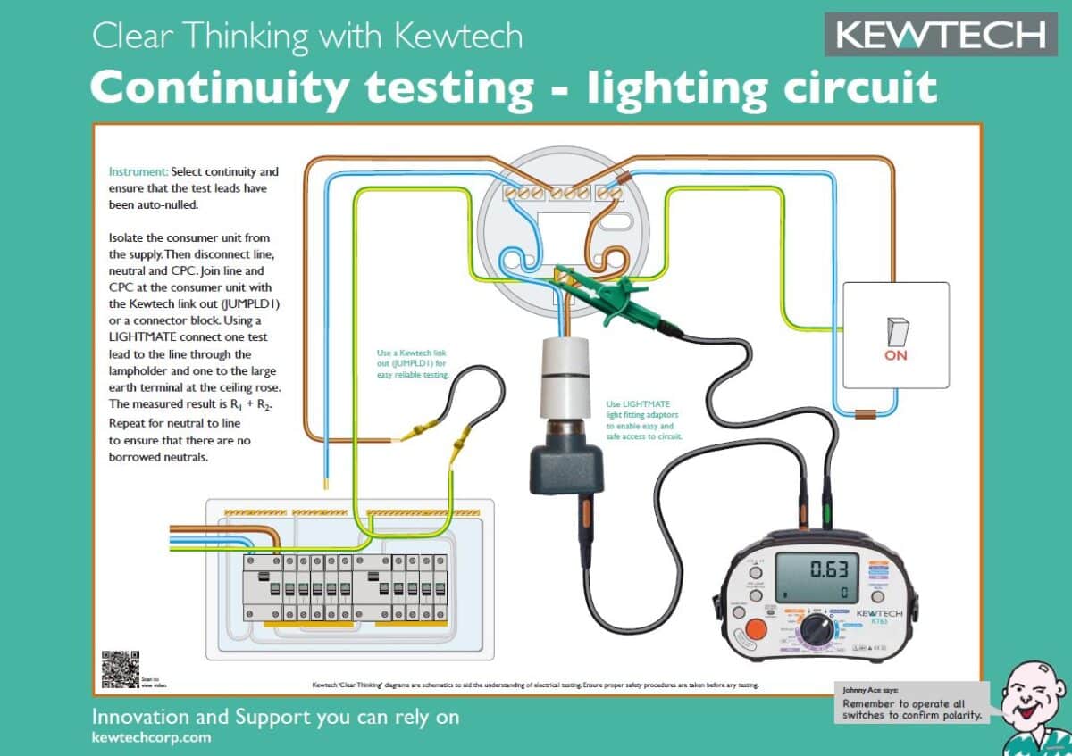
Electrical Fundamentals Kewtech
Step-by-Step
3. The Art of the Beep
Alright, now for the fun part! Here's a step-by-step guide to performing a continuity test: First, make sure the circuit is completely de-energized. We can't stress this enough! Safety first, remember? Double-check that the power is off before you proceed. This is important, so triple-check it!
Next, turn on your multimeter and select the continuity testing mode. This mode is usually indicated by a diode symbol (a triangle with a line) or a speaker symbol. If you're not sure which mode to use, consult your multimeter's manual. Some multimeters have an auto-ranging feature that automatically selects the appropriate range, while others require you to select the range manually. Now is the time to select the range. Usually you can start high and work your way down.
Now, touch the two test leads together. This should produce a beep or a reading of zero ohms (or close to it) on the multimeter's display. This confirms that the multimeter is working correctly and that the test leads are making good contact. If you don't hear a beep or see a reading of zero, check the battery in your multimeter or try a different set of test leads.
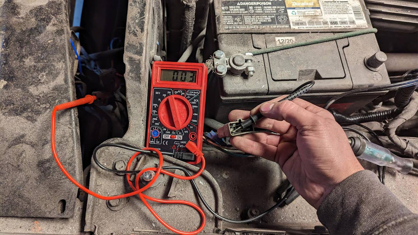
Finally, place one test lead on one end of the wire or component you want to test and the other test lead on the other end. If you hear a beep or see a reading of zero ohms, it means there is continuity, and the circuit is complete. If you don't hear a beep or see a reading of infinity (or OL on some multimeters), it means there is no continuity, and the circuit is broken. And that's it! You've successfully performed a continuity test. Wasn't that easy?

Continuity Test Electrical Wiring Wire
Interpreting the Results
4. Decoding the Signals
So, you've performed the test, and your multimeter is either beeping like a happy little robot or staying stubbornly silent. What does it all mean? A beep (or a reading of zero ohms) indicates that there's a continuous path for electricity to flow. This means the wire, fuse, switch, or whatever you're testing is likely in good working order. Hooray!
On the other hand, silence (or a reading of infinity) means there's a break in the circuit. Something is preventing electricity from flowing from one end to the other. This could be a broken wire, a blown fuse, a faulty switch, or a loose connection. The exact cause will depend on what you're testing and where you're testing it.
It's important to remember that continuity testing only tells you if there's a complete path or not. It doesn't tell you anything about the quality of the connection. A wire might have continuity, but if it's corroded or damaged, it might not be able to carry enough current to power a device. So, always visually inspect wires and components for signs of damage or wear.
Also, be aware of what you're testing. Some components, like resistors and capacitors, will show a resistance value even when they're working correctly. Consult the component's datasheet or schematic to determine the expected resistance value. Continuity testing is a powerful tool, but it's not a magic bullet. Use it in conjunction with other troubleshooting techniques to diagnose electrical problems effectively.
How To Perform An Electrical Continuity Test Wiring Work
Common Mistakes and How to Avoid Them
5. Staying Out of Trouble
Even though continuity testing is relatively straightforward, it's easy to make mistakes. One of the most common errors is forgetting to de-energize the circuit. Testing a live circuit with a multimeter can damage the meter and, more importantly, put you at risk of electric shock. Always, always, always turn off the power before you start testing. Seriously, we can't say that enough!
Another common mistake is using faulty test leads. Frayed wires, loose connectors, or corroded tips can all lead to inaccurate readings. Before you start testing, inspect your test leads carefully and make sure they're in good condition. If you suspect they're damaged, replace them with a new set.
Also, make sure you're using the correct settings on your multimeter. Selecting the wrong mode or range can lead to misleading results. Consult your multimeter's manual to ensure you're using the correct settings for continuity testing. If your multimeter has an auto-ranging feature, use it! It can save you a lot of headaches.
Finally, don't assume that continuity means everything is okay. As we mentioned earlier, a wire might have continuity but still be unable to carry enough current to power a device. Always visually inspect wires and components for signs of damage or wear. Continuity testing is just one piece of the puzzle. Use it in conjunction with other troubleshooting techniques to get a complete picture of the circuit's health.

FAQ
6. Frequently Asked Questions About Electrical Continuity Testing
Q: What does it mean if my multimeter shows a very high resistance instead of infinity when testing for continuity?A: A very high resistance reading (but not quite infinity) can indicate a poor connection or a component with some inherent resistance. Check your test lead connections, and if testing a component, consult its datasheet to see what the expected resistance should be.
Q: Can I test for continuity on a circuit board with components still attached?A: Yes, but be cautious. Other components in the circuit can sometimes affect the continuity reading. If possible, isolate the component you're testing by disconnecting it from the circuit.
Q: My multimeter doesn't have a continuity setting. Can I still test for continuity using the resistance setting?A: Yes, you can. Select the lowest resistance range on your multimeter. If the resistance reading is close to zero, there's likely good continuity. However, a dedicated continuity setting with a beep is generally easier to use.
Q: Is continuity testing the same as testing for a short circuit?A: While both involve low resistance paths, they are different concepts. Continuity testing verifies an intended path, while testing for a short circuit looks for unintended low resistance paths that bypass normal circuit components. A short circuit is generally a fault condition.